

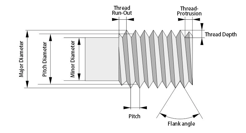
Thread Turning - Precision in Metal Cutting

Related Products
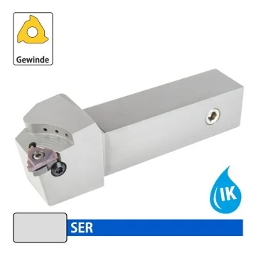
External Tool Holder - SER... Right - with cooling holes
Price
ab €129.00
Availability: 214748362 In Stock
| External Tool Holder | SER |
| Insert | 16/22 ER |
| Main application | Threading |
| Right/Left | Right |
| Clamping | Screw Clamp |
| Cooling | With Cooling Holes |
| Packaging Unit | 1 Pc. |
| H | h | L | B | f | |
| SER 1616 F16-H | 16 | 16 | 80 | 16 | 20 |
| SER 2020 H16-H | 20 | 20 | 100 | 20 | 25 |
| SER 2525 K16-H | 25 | 25 | 125 | 25 | 32 |
| SER 3232 K16-H | 32 | 32 | 125 | 32 | 40 |
| SER 2525 K22-H | 25 | 25 | 125 | 25 | 32 |
| SER 3232 K22-H | 32 | 32 | 125 | 32 | 40 |
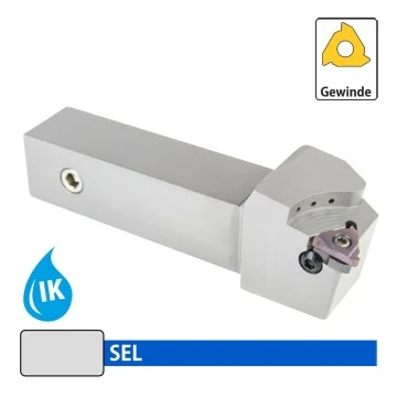
External Threading Tool Holder - SEL... Left - with cooling holes
Price
ab €129.00
Availability: 214748364 In Stock
| External Tool Holder | SEL |
| Insert | 16/22 EL |
| Main application | Threading |
| Right/Left | Left |
| Clamping | Screw Clamp |
| Cooling | With Cooling Holes |
| Packaging Unit | 1 Pc. |
| H | h | L | B | f | |
| SEL 1616 F16-H | 16 | 16 | 80 | 16 | 20 |
| SEL 2020 H16-H | 20 | 20 | 100 | 20 | 25 |
| SEL 2525 K16-H | 25 | 25 | 125 | 25 | 32 |
| SEL 3232 K16-H | 32 | 32 | 125 | 32 | 40 |
| SEL 2525 K22-H | 25 | 25 | 125 | 25 | 32 |
| SEL 3232 K22-H | 32 | 32 | 125 | 32 | 40 |
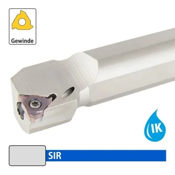
Internal Threading Tool Holder - SIR Right - with cooling holes
Price
ab €58.00
Availability: 214748352 In Stock
| Boring Bar | SIR |
| Insert | 11/16/22 IR |
| Right/Left | Right |
| Main application | Threading |
| Clamping | Screw Clamp |
| Cooling | With Cooling Hole |
| Packaging Unit | 1 Pc. |
| d | b | L | h | f | L1 | Dmin | |
| SIR-16 K11-H | 16 | 15,5 | 125 | 15 | 10 | 20,9 | 12 |
| SIR-16 M11-H | 16 | 16 | 150 | 15 | 10,5 | 25,9 | 16 |
| SIR-16 M16-H | 16 | 15,5 | 150 | 15 | 12 | 27 | 20 |
| SIR-20 M16-H | 20 | 19 | 150 | 18 | 14 | 28,7 | 25 |
| SIR-20 Q16-H | 20 | 19 | 180 | 18 | 14 | 34 | 25 |
| SIR-25 M16-H | 25 | 24 | 150 | 23 | 17 | 28,8 | 32 |
| SIR-32 R16-H | 32 | 31 | 200 | 30 | 22 | 30,9 | 40 |
| SIR-32 S16-H | 32 | 31 | 250 | 30 | 22 | 30,9 | 40 |
| SIR-40 T16-H | 40 | 38,5 | 300 | 37 | 27 | 31,5 | 50 |
| SIR-20 Q22-H | 20 | 19 | 180 | 18 | 15 | 35 | 25 |
| SIR-25 R22-H | 25 | 24 | 200 | 23 | 19 | 39 | 32 |
| SIR-32 S22-H | 32 | 31 | 250 | 30 | 22 | 36,4 | 40 |
| SIR-40 T22-H | 40 | 38,5 | 300 | 37 | 27 | 37,2 | 50 |
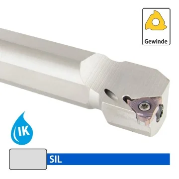
Internal Threading Tool Holder - SIL... Left - with cooling holes
Price
ab €58.00
Availability: 214748362 In Stock
| Boring Bar | SIL/TIL |
| Insert | 11/16/22 IL |
| Main application | Threading |
| Right/Left | Left |
| Clamping | Screw Clamp |
| Cooling | Without Cooling Holes |
| Packaging Unit | 1 Pc. |
| d | b | L | h | f | L1 | Dmin | Insert | |
| SIL-16 K11-H | 16 | 15,5 | 125 | 15 | 10 | 20,9 | 12 | 11 IL |
| SIL-16 M11-H | 16 | 16 | 150 | 15 | 10,5 | 25,9 | 16 | 11 IL |
| SIL-16 M16-H | 16 | 15,5 | 150 | 15 | 12 | 27 | 20 | 11 IL |
| SIL-20 M16-H | 20 | 19 | 150 | 18 | 14 | 28,7 | 25 | 16 IL |
| SIL-20 Q16-H | 20 | 19 | 180 | 18 | 14 | 34 | 25 | 16 IL |
| SIL-25 M16-H | 25 | 24 | 150 | 23 | 17 | 28,8 | 32 | 16 IL |
| SIL-32 R16-H | 32 | 31 | 200 | 30 | 22 | 30,9 | 40 | 16 IL |
| SIL-32 S16-H | 32 | 31 | 250 | 30 | 22 | 30,9 | 40 | 16 IL |
| SIL-40 T16-H | 40 | 38,5 | 300 | 37 | 27 | 31,5 | 50 | 16 IL |
| SIL-20 Q22-H | 20 | 19 | 180 | 18 | 15 | 35 | 25 | 22 IL |
| SIL-25 R22-H | 25 | 24 | 200 | 23 | 19 | 39 | 32 | 22 IL |
| SIL-32 S22-H | 32 | 31 | 250 | 30 | 22 | 36,4 | 40 | 22 IL |
| SIL-40 T22-H | 40 | 38,5 | 300 | 37 | 27 | 37,2 | 50 | 22 IL |

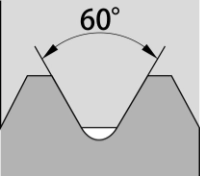
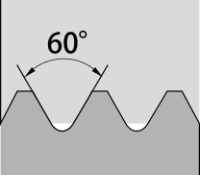
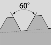
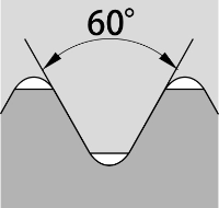
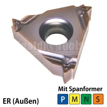
Threading insert - 16ER (60°) Metric Full Profile Universal RT315
Price
ab €8.70
Availability: 2147483395 In Stock
| Insert size | 16 |
| Inside/Outside Thread | Outside |
| Direction | Right |
| Thread Type | Metric |
| Profile | Full profile |
| Workpiece Materials | Steel, Stainless Steel, Special Materials, NF-Metals |
| Flank angle | 60° |
| Grade | RT315: PVD-coated P15-P25 and M10-M25 solid carbide for universal use |
| Packaging Unit | 2 pc. |
| ISO | Pitch | I.C | S | d | |
| 16ER-V-ISO-1,0-G RT315 | 16 | 1,0mm | 9,525 | 3,52 | 4 |
| 16ER-V-ISO-1,25-G RT315 |
16 | 1,25mm | 9,525 | 3,52 | 4 |
| 16ER-V-ISO-1,5-G RT315 |
16 | 1,5mm | 9,525 | 3,52 | 4 |
| 16ER-V-ISO-1,75-G RT315 |
16 | 1,75mm | 9,525 | 3,52 | 4 |
| 16ER-V-ISO-2,0-G RT315 |
16 | 2,0mm | 9,525 | 3,52 | 4 |
| 16ER-V-ISO-2,5-G RT315 |
16 | 2,5mm | 9,525 | 3,52 | 4 |
| 16ER-V-ISO-3,0-G RT315 |
16 | 3,0mm | 9,525 | 3,52 | 4 |
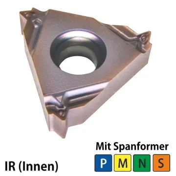
Threading insert - 16IR (60°) Metric Full Profile Universal RT315
Price
ab €8.70
Availability: 214748306 In Stock
| Insert size | 16 |
| Inside/Outside Thread | Inside |
| Direction | Right |
| Thread Type | Metric |
| Profile | Full profile |
| Workpiece Materials | Steel, Stainless Steel, Special Materials, NF-Metals |
| Flank angle | 60° |
| Grade | RT315: PVD-coated P15-P25 and M10-M25 for universal use |
| Packaging Unit | 2 pc. |
| ISO | Pitch | I.C | S | d | |
| 16IR-V-ISO-1,0-G RT315 | 16 | 1,0 mm | 9,525 | 3,52 | 4 |
| 16IR-V-ISO-1,25-G RT315 |
16 | 1,25 mm | 9,525 | 3,52 | 4 |
| 16IR-V-ISO-1,5-G RT315 |
16 | 1,5 mm | 9,525 | 3,52 | 4 |
| 16IR-V-ISO-1,75-G RT315 |
16 | 1,75 mm | 9,525 | 3,52 | 4 |
| 16IR-V-ISO-2,0-G RT315 |
16 | 2,0 mm | 9,525 | 3,52 | 4 |
| 16IR-V-ISO-2,5-G RT315 |
16 | 2,5 mm | 9,525 | 3,52 | 4 |
| 16IR-V-ISO-3,0-G RT315 |
16 | 3,0 mm | 9,525 | 3,52 | 4 |
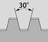
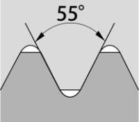
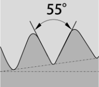
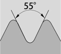
Threading insert - 16ER (55°) Imperial partial Profile Universal RT315
Price
ab €8.70
Availability: 214748352 In Stock
| Insert size | 16 |
| Inside/Outside Thread | Outside |
| Direction | Right |
| Thread Type | Imperial |
| Profile | Part Profile |
| Workpiece Materials | Steel, Stainless Steel, Special Materials, NF-Metals |
| Flank angle | 55° |
| Grade | RT315: PVD-coated P15-P25 and M10-M25 solid carbide for universal use |
| Packaging Unit | 2 pc. |
| ISO | TPI | I.C. | S | d | |
| 16ER-T-A55-G RT315 |
16 | 48-16 TPI | 9,525 | 3,52 | 4 |
| 16ER-T-AG55-G RT315 |
16 | 48-8 TPI | 9,525 | 3,52 | 4 |
| 16ER-T-G55-G RT315 |
16 | 14-8 TPI | 9,525 | 3,52 | 4 |

Threading insert - 16IR (55°) Imperial partial Profile Universal RT315
Price
ab €8.70
Availability: 214748364 In Stock
| Insert size | 16 |
| Inside/Outside Thread | Inside |
| Direction | Right |
| Thread Type | Imperial |
| Profile | Part Profile |
| Workpiece Materials | Steel, Stainless Steel, Special Materials, NF-Metals |
| Flank angle | 55° |
| Grade | RT315: PVD-coated P15-P25 and M10-M25 solid carbide for universal use |
| Packaging Unit | 2 pc. |
| ISO | TPI | I.C. | S | d | |
| 16IR-T-AG55-G RT315 |
16 | 48-16 TPI | 9,525 | 3,52 | 4 |
| 16IR-T-AG55-G RT315 |
16 | 48-8 TPI | 9,525 | 3,52 | 4 |
| 16IR-T-AG55-G RT315 |
16 | 14-8 TPI | 9,525 | 3,52 | 4 |