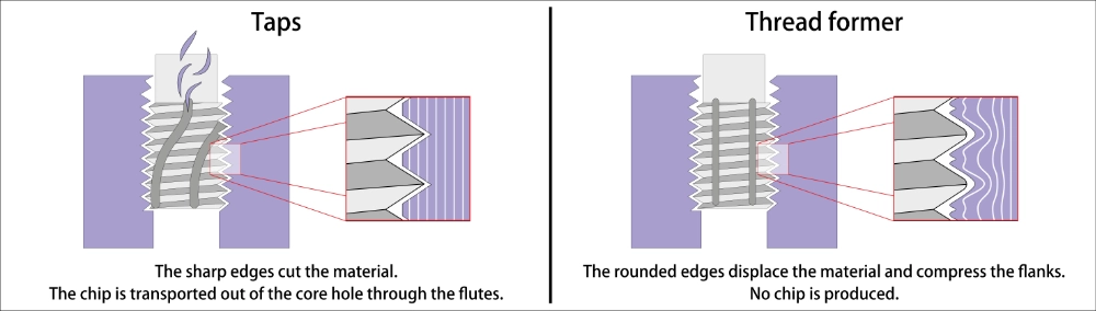
Tap vs. Thread Former - Advantages and Disadvantages of Both Systems
1 - Thread Taps - The Cutting Process
- Operating Principle and Design
Taps are cutting tools that remove material through a screwing motion and cut the thread profile into the workpiece. The conventional tap consists of a cylindrical base body with spirally arranged cutting edges that create the thread through machining.
- Design Features:
The chamfer forms the front area of the tap and significantly determines the cutting behavior. Depending on the chamfer length, different types are distinguished: short chamfer (2-3 threads) for through holes, medium chamfer (4-5 threads) for universal applications, and long chamfer (6-8 threads) for blind holes.
The flute spaces between the cutting edges collect the generated chips and transport them away. Their design decisively influences chip evacuation and thus process reliability.
The guide section (calibrating area) ensures dimensional accuracy and guidance in the already cut thread. It typically encompasses 3-4 complete thread turns.
Tool Geometry and Cutting Material Selection
- Rake and Relief Angles:
The rake angles range between 8° and 15° depending on the application. Larger rake angles reduce cutting forces but can impair cutting edge stability. The relief angle is usually 6-12° and prevents rubbing of the relief surfaces.
- Cutting Material Selection:
HSS (High Speed Steel): Standard for most applications, good toughness
HSS-E (kobaltlegiert): For difficult-to-machine materials and higher cutting speeds
HSS-PM (pulvermetallurgisch): Highest wear resistance for demanding applications
Hartmetall: For very high cutting speeds, mainly in series production
- Applications and Materials
Taps are suitable for practically all metallic materials:
- Steel: From soft structural steels to high-strength heat-treated steels. For higher-strength steels, special HSS-E grades or coated tools are required.
- Stainless Steels: Require special attention due to their tendency to work harden. Sharp cutting edges and continuous feed are essential.
- Cast materials: Gray cast iron machines well, while ductile iron places higher demands on tool quality.
- Non-ferrous metals: Aluminum, copper and their alloys are usually easy to tap, but require adapted geometries to avoid built-up edges.
- Process Parameters and Coolant/Lubrification
Cutting Speed: The optimal cutting speed depends heavily on the material. For steel, typical values range between 5-25 m/min, for aluminum significantly higher at 50-150 m/min.
Coolant/Lubrication: Eine effektive Kühlschmierung ist beim Gewindebohren essentiell. Sie erfüllt mehrere Funktionen: Kühlung der Schneidkanten, Schmierung zur Reibungsreduzierung und Spülung der Späne aus den Spanräumen. Wasserlösliche KSS eignen sich für die meisten Anwendungen, während bei problematischen Werkstoffen hochwertige Schneidöle bessere Ergebnisse liefern.-
2 -Thread forming - The Chipless Process
Operating Principle and Construction
Thread forming tools create threads through plastic deformation of the material without chip formation. The tool displaces the material to the side while forming the thread contour. This process requires sufficient ductility of the workpiece material and precisely matched pilot hole drilling.
Design Features:
The forming section at the tool beginning gradually displaces the material and forms the thread contour. Unlike thread cutting taps, there are no sharp cutting edges present, but rather profiled forming flanks that progressively shape the thread profile through controlled plastic deformation.
The guiding section stabilizes the tool within the already formed thread and ensures dimensional accuracy. This section maintains the thread pitch and prevents the tool from wandering during the forming process.
Special Surface Treatment: Thread forming tools typically receive special surface treatments such as nitriding or TiN coating to reduce friction and increase tool life. These treatments create a hard, smooth surface that minimizes galling and wear during the forming process.
Material Requirements and Limitations
Suitable Materials
Thread forming tools are particularly suitable for ductile materials with sufficient deformability:
- Structural steels up to approximately 800 N/mm² tensile strength
- Free-machining steels
- Non-ferrous metals such as aluminum, brass, copper
- Softer stainless steels (austenitic grades)
The key requirement is that the material must be able to undergo plastic deformation without cracking or work hardening excessively during the forming process.
Unsuitable Materials
- Brittle materials (cast iron, hardened steels)
- Very hard alloys
- Materials with high work hardening tendency
- Titanium and its alloys
These materials either lack the necessary ductility for plastic deformation or exhibit characteristics that prevent successful thread forming.
Pilot Hole Calculation
The pilot hole size is more critical in thread forming than in thread cutting, as the displaced material must form the thread core. The calculation must account for material displacement and flow characteristics.
Calculation Formula: Pilot Hole Diameter = Nominal Diameter - Pitch + Material Constant
The material constant takes into account the specific deformation properties and typically ranges between 0.1-0.3 mm, depending on the material type and its deformation characteristics. For softer materials like aluminum, the constant tends toward the lower end of the range, while for harder steels, it approaches the upper limit.
3 - Direct Comparison: Taps vs. Thread Formers
Process Quality and Thread Strength
Surface Quality
Thread forming tools produce a smooth, work-hardened surface through plastic deformation without machining marks. Surface roughness typically ranges from Ra 0.8-1.6 μm. Thread cutting taps, in contrast, leave cutting marks with roughness values of Ra 1.6-6.3 μm.
Thread Strength
Through work hardening during the forming process, formed threads achieve 15-30% higher pull-out strength compared to cut threads. The continuous fiber flow without interruption additionally contributes to higher strength.
Dimensional Accuracy
Both processes achieve tolerance class 6H when properly applied. However, thread forming tools tend to show dimensional deviations due to springback when used on unsuitable materials.
Economic Aspects
Tool Costs
Thread forming tools are approximately 20-50% more expensive to purchase than comparable thread cutting taps. However, these additional costs are amortized through higher tool life.
Tool Life
Thread forming tools typically achieve 3-10 times higher tool life than thread cutting taps, as no wear processes occur at cutting edges. The main wear cause is abrasive stress on the forming flanks.
Processing Speed
Thread forming tools can be operated at 2-3 times higher speeds, as no chips are generated and heat development is lower.
Auxiliary Times
The elimination of chip disposal and reduced coolant requirements significantly reduce auxiliary times.
Process Reliability and Handling
Breakage Risk
Thread forming tools are less prone to breakage, as they tend to deform plastically rather than break brittlely when overloaded. Thread cutting taps can fail spontaneously with incorrect parameters or chip problems.
Cooling and Lubrication
Thread forming requires only minimal cooling and lubrication, primarily for lubrication purposes. Thread cutting requires intensive cooling and lubrication for chip and heat removal.
Chip Problems
Chipless machining completely eliminates problems with chip jamming and chip breaking. This is particularly advantageous for blind holes and automated processes.
Application Limits and Restrictions
Material Spectrum
Thread cutting taps have a significantly broader application spectrum and can process virtually all metallic materials. Thread forming tools are limited to ductile materials.
Thread Sizes
Both processes cover the M3-M20 range well. For very small threads (< M3), thread cutting taps are more stable; for large threads (> M20), forming forces become critical in forming.
Workpiece Geometry
Thread forming is only possible in stable, thick-walled components. Thin-walled parts can be deformed or damaged by the forming forces.
Decision Criteria for Process Selection
Material-Based Selection
Thread cutting taps are preferred for:
- Hard materials (> 250 HB)
- Brittle materials (cast iron, hardened steels)
- Difficult-to-deform alloys
- Unknown material properties
Thread forming tools are preferred for:
- Soft to medium-hard steels (< 800 N/mm²)
- Free-machining steels
- Non-ferrous metals
- High ductility required
Quality Requirements
- High surface quality: Thread forming tools preferred
- Maximum strength: Thread forming tools preferred
- Tight tolerances with difficult materials: Thread cutting taps preferred
Economic Considerations
- Large quantities: Thread forming tools usually more economical
- Small series: Thread cutting taps more flexible
- Fully automated production: Thread forming tools preferred due to absence of chips
Modern Developments and Special Forms
Hybrid Tools
Modern developments combine both processes: thread cutting taps with partial forming zones or thread forming tools with cutting edges for difficult materials.
Coating Technologies
Both thread cutting taps and thread forming tools benefit from modern PVD coatings:
- TiN for universal applications
- TiAlN for higher temperatures
- DLC (Diamond Like Carbon) for aluminum
Special Constructions
- Spiral thread cutting taps: Improved chip removal through spiral flutes
- Internal cooling: Targeted coolant supply directly to cutting edges
- Variable pitch: Optimized force distribution over tool length
Conclusion and Recommendations
The choice between thread cutting taps and thread forming tools should be based on a holistic consideration that takes into account material, quality requirements, quantity, and economic aspects.
Thread cutting taps remain the first choice for:
- Universal applications with changing materials
- Hard and brittle materials
- Small series and prototype production
- Repair and maintenance work
Thread forming tools are optimal for:
- Large series in suitable materials
- Highest quality requirements for strength and surface
- Fully automated production lines
- Cost-optimized series production
The continuous development of both technologies constantly expands their application areas and improves achievable quality and economy. A thorough knowledge of both processes enables optimal selection for each specific application.
Related Products
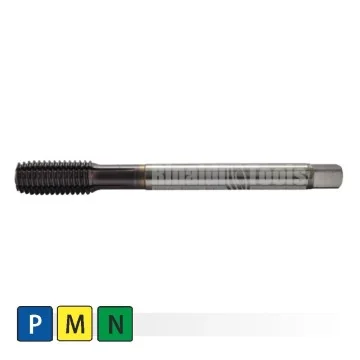
HSS-E Forming Tap - Metrical 60°
| Tap type | Forming Tap |
| Gewinde | Metrical 60° |
| Workpiece Materials | Steel, Stainless Steel, NF-Materials |
| Grade | HSS-E TiALN |
| Packaging Unit | 1 pc. |
| D | P | L | L2 | L4 | d | K | Kl | |
| GF M2,5x0,45-HSS-E TiAlN | M2,5 | 0,45 | 50 | 9 | 15 | 2,8 | 2,1 | 5 |
| GF M3x0,5-HSS-E TiAlN | M3 | 0,5 | 56 | 11 | 18 | 3,5 | 2,7 | 6 |
| GF M3,5x0,6-HSS-E TiAlN | M3,5 | 0,6 | 56 | 12 | 20 | 4 | 3 | 6 |
| GF M4x0,7-HSS-E TiAlN | M4 | 0,7 | 63 | 13 | 21 | 4,5 | 3,4 | 6 |
| GF M4,5x0,75-HSS-E TiAlN | M4,5 | 0,75 | 70 | 14 | 25 | 6 | 4,9 | 8 |
| GF M5x0,8-HSS-E TiAlN | M5 | 0,8 | 70 | 15 | 25 | 6 | 4,9 | 8 |
| GF M6x1-HSS-E TiAlN | M6 | 1 | 80 | 17 | 30 | 6 | 4,9 | 8 |
| GF M8x1,25-HSS-E TiAlN | M8 | 1,25 | 90 | 20 | 35 | 8 | 6,2 | 9 |
| GF M10x1,5-HSS-E TiAlN | M10 | 1,5 | 100 | 22 | 39 | 10 | 8 | 11 |
| GF M12x1,75-HSS-E TiAlN | M12 | 1,75 | 110 | 24 | 44 | 9 | 7 | 10 |
| GF M16x2-HSS-E TiAlN | M16 | 2 | 110 | 27 | 44 | 12 | 9 | 12 |
HSS-E-Tap blind hole, metric 60°
| Tap Type | HSS-E |
| Hole | Blind Hole |
| Thread | Metric |
| Workpiece Materials | Steel, Stainless Steel, Cast Iron, NF-Materials |
| Flank Angle | 60° |
| Packaging unit | 1 Pc. |
| D | P | L2 | L | L4 | d | K | Kl | Z | |
| GB-S-ISO-M3-HSS-E-TIN | M3 | 0,5 | 6 | 56 | 18 | 3,5 | 2,7 | 6 | 3 |
| GB-S-ISO-M4-HSS-E-TIN | M4 | 0,7 | 7 | 63 | 21 | 4,5 | 3,4 | 6 | 3 |
| GB-S-ISO-M5-HSS-E-TIN | M5 | 0,8 | 8 | 70 | 25 | 6 | 4,9 | 8 | 3 |
| GB-S-ISO-M6-HSS-E-TIN | M6 | 1 | 10 | 80 | 30 | 6 | 4,9 | 8 | 3 |
| GB-S-ISO-M8-HSS-E-TIN | M8 | 1,25 | 13 | 90 | 35 | 8 | 6,2 | 9 | 3 |
| GB-S-ISO-M10-HSS-E-TIN | M10 | 1,5 | 15 | 100 | 39 | 10 | 8 | 11 | 3 |
| GB-S-ISO-M12-HSS-E-TIN | M12 | 1,75 | 18 | 110 | 44 | 9 | 7 | 10 | 3 |
| GB-S-ISO-M16-HSS-E-TIN | M16 | 2 | 20 | 110 | 44 | 12 | 9 | 12 | 3 |
| GB-S-ISO-M20-HSS-E-TIN | M20 | 2,5 | 25 | 140 | 54 | 16 | 12 | 15 | 4 |
| GB-S-ISO-M24-HSS-E-TIN | M24 | 3 | 30 | 160 | 60 | 18 | 14.5 | 17 | 4 |
| GB-S-ISO-M30-HSS-E-TIN | M30 | 3,5 | 35 | 180 | 70 | 22 | 18 | 21 | 4 |
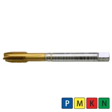
HSS-E-Tap through hole, metric 60°
| Tap Typ | HSS-E |
| Hole | Trough Hole |
| Thread | Metric |
| Materials | Steel, Stainless Steel, Cast Iron, NF-Materials |
| Flank Angle | 60° |
| Packaging unit | 1 Pc. |
| Thread/D | P | L2 | L | L4 | d | Z | K | Kl | |
| GB-D-ISO-M3-HSS-E-TIN | M3 | 0,5 | 11 | 56 | 18 | 3,5 | 3 | 2,7 | 6 |
| GB-D-ISO-M4-HSS-E-TIN | M4 | 0,7 | 13 | 63 | 21 | 4,5 | 3 | 3,4 | 6 |
| GB-D-ISO-M5-HSS-E-TIN | M5 | 0,8 | 15 | 70 | 25 | 6 | 3 | 4,9 | 8 |
| GB-D-ISO-M6-HSS-E-TIN | M6 | 1 | 17 | 80 | 30 | 6 | 3 | 4,9 | 8 |
| GB-D-ISO-M8-HSS-E-TIN | M8 | 1,25 | 20 | 90 | 35 | 8 | 3 | 6,2 | 9 |
| GB-D-ISO-M10-HSS-E-TIN | M10 | 1,5 | 22 | 100 | 39 | 10 | 3 | 8 | 11 |
| GB-D-ISO-M12-HSS-E-TIN | M12 | 1,75 | 24 | 110 | 44 | 9 | 3 | 7 | 10 |
| GB-D-ISO-M16-HSS-E-TIN | M16 | 2 | 27 | 110 | 44 | 12 | 3 | 9 | 12 |
| GB-D-ISO-M20-HSS-E-TIN | M20 | 2,5 | 32 | 140 | 54 | 16 | 4 | 12 | 15 |
| GB-D-ISO-M24-HSS-E-TIN | M24 | 3 | 34 | 160 | 60 | 18 | 4 | 14,5 | 17 |
| GB-D-ISO-M30-HSS-E-TIN | M30 | 3,5 | 40 | 180 | 70 | 22 | 4 | 18 | 21 |
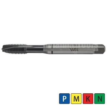
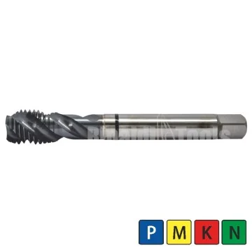
HSS-PM-Tap, blind hole, metric 60°
| Tap Type | HSS-PM |
| Hole | Blind Hole |
| Thread | Metric |
| Materials | Steel, Stainless Steel, Cast Iron and NF-Materials |
| Flank Angle | 60° |
| Packaging unit | 1 Pc. |
| Thread/D | P | L2 | L | L4 | d | K | Kl | Z | |
| GB-S-M2-HSS-PM-TiALN | M2 | 0,4 | 3,2 | 45 | 13 | 2,8 | 2,1 | 5 | 2 |
| GB-S-M2,5-HSS-PM-TiALN | M2,5 | 0,45 | 3,6 | 50 | 15 | 2,8 | 2,1 | 5 | 2 |
| GB-S-M3-HSS-PM-TiALN | M3 | 0,5 | 4 | 56 | 18 | 3,5 | 2,7 | 6 | 3 |
| GB-S-M3,5-HSS-PM-TiALN | M3,5 | 0,6 | 4,8 | 56 | 20 | 4 | 3 | 6 | 3 |
| GB-S-M4-HSS-PM-TiALN | M4 | 0,7 | 5,6 | 63 | 21 | 4,5 | 3,4 | 6 | 3 |
| GB-S-M5-HSS-PM-TiALN | M5 | 0,8 | 6,4 | 70 | 25 | 6 | 4,9 | 8 | 3 |
| GB-S-M6-HSS-PM-TiALN | M6 | 1 | 8 | 80 | 30 | 6 | 4,9 | 8 | 3 |
| GB-S-M8-HSS-PM-TiALN | M8 | 1,25 | 13 | 90 | 35 | 8 | 6,2 | 9 | 3 |
| GB-S-M10-HSS-PM-TiALN | M10 | 1,5 | 15 | 100 | 39 | 10 | 8 | 11 | 3 |
| GB-S-M12-HSS-PM-TiALN | M12 | 1,75 | 18 | 110 | 44 | 9,0 | 7 | 10 | 3 |
| GB-S-M14-HSS-PM-TiALN | M14 | 2 | 20 | 110 | 44 | 11 | 9 | 12 | 3 |
| GB-S-M16-HSS-PM-TiALN | M16 | 2 | 20 | 110 | 44 | 12 | 9 | 12 | 3 |
| GB-S-M18-HSS-PM-TiALN | M18 | 2,5 | 25 | 125 | 50 | 14 | 11 | 14 | 4 |
| GB-S-M20-HSS-PM-TiALN | M20 | 2,5 | 25 | 140 | 54 | 16 | 12 | 15 | 4 |
| GB-S-M22-HSS-PM-TiALN | M22 | 2,5 | 25 | 140 | 54 | 18 | 14,5 | 17 | 4 |
| GB-S-M24-HSS-PM-TiALN | M24 | 3 | 30 | 160 | 60 | 18 | 14,5 | 17 | 4 |
HSS-PM-Tap through hole, metric 60°
| Tap Typ | HSS-PM |
| Hole | Trough Hole |
| Thread | Metric |
| Materials | Steel, Stainless Steel, Cast Iron and NF-Materials |
| Flank Angle | 60° |
| Packaging unit | 1 Pc. |
| Thread/D | P | L2 | L | L4 | d | Z | K | Kl | |
| GB-D-M2-HSS-PM-TiALN | M2 | 0,4 | 8 | 45 | 13 | 2,8 | 2 | 2,1 | 5 |
| GB-D-M2,5-HSS-PM-TiALN | M2,5 | 0,45 | 9 | 50 | 15 | 2,8 | 2 | 2,1 | 5 |
| GB-D-M3-HSS-PM-TiALN | M3 | 0,5 | 11 | 56 | 18 | 3,5 | 3 | 2,7 | 6 |
| GB-D-M3,5-HSS-PM-TiALN | M3,5 | 0,6 | 12 | 56 | 20 | 4 | 3 | 3 | 6 |
| GB-D-M4-HSS-PM-TiALN | M4 | 0,7 | 13 | 63 | 21 | 4,5 | 3 | 3,4 | 6 |
| GB-D-M5-HSS-PM-TiALN | M5 | 0,8 | 15 | 70 | 25 | 6 | 3 | 4,9 | 8 |
| GB-D-M6-HSS-PM-TiALN | M6 | 1 | 17 | 80 | 30 | 6 | 3 | 4,9 | 8 |
| GB-D-M8-HSS-PM-TiALN | M8 | 1,25 | 20 | 90 | 35 | 8 | 3 | 6,2 | 9 |
| GB-D-M10-HSS-PM-TiALN | M10 | 1,5 | 22 | 100 | 39 | 10 | 3 | 8 | 11 |
| GB-D-M12-HSS-PM-TiALN | M12 | 1,75 | 24 | 110 | 44 | 9 | 3 | 7 | 10 |
| GB-D-M14-HSS-PM-TiALN | M14 | 2 | 26 | 110 | 44 | 11 | 3 | 9 | 12 |
| GB-D-M16-HSS-PM-TiALN | M16 | 2 | 27 | 110 | 44 | 12 | 3 | 9 | 12 |
| GB-D-M18-HSS-PM-TiALN | M18 | 2,5 | 30 | 125 | 50 | 14 | 3 | 11 | 14 |
| GB-D-M20-HSS-PM-TiALN | M20 | 2,5 | 32 | 140 | 54 | 16 | 3 | 12 | 15 |
| GB-D-M22-HSS-PM-TiALN | M22 | 2,5 | 32 | 140 | 54 | 18 | 3 | 14,5 | 17 |
| GB-D-M24-HSS-PM-TiALN | M24 | 3 | 34 | 160 | 60 | 18 | 3 | 14,5 | 17 |
HSS-PM-Tap blind hole, metric 60°, fine thread
| Tap Typ | HSS-PM |
| Hole | Blind Hole |
| Thread | Metric, Fine thread |
| Materials | Steel, Stainless Steel, Cast Iron and NF-Materials |
| Flank Angle | 60° |
| Packaging unit | 1 Pc. |
HSS-PM-Tap through hole, metric 60°, fine thread
| Tap Typ | HSS-PM |
| Hole | Trough Hole |
| Thread | Metric, Fine Thread |
| Materials | Steel, Stainless Steel, Cast Iron and NF-Materials |
| Flank Angle | 60° |
| Packaging unit | 1 Pc. |